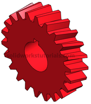
In this solidworks tutorial, you will create helical gear.
1. Click New. ![]() Click Part,
Click Part, ![]() OK.
OK.
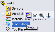
2. Click Front Plane and click on Sketch.
3. Click Circle ![]() and sketch a circle center at origin. Click Smart Dimension,
and sketch a circle center at origin. Click Smart Dimension,  click sketched circle and set it diameter to 1.0in.
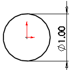
4. You just completed your sketch, let’s build feature from it. Click Features>Extruded Boss/Base. 
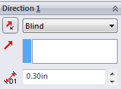 Set D1 to 0.3in
 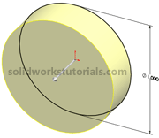 and
and ![]() .
.
5. Click on front face and click Normal To.
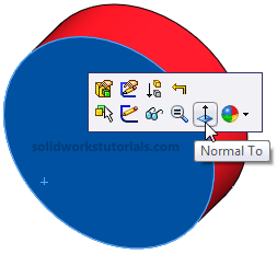
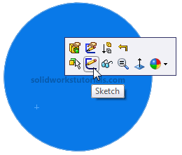
6. Click on front face and click Sketch.
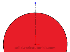
7. Click on Centerline  and sketch vertical Centerline.
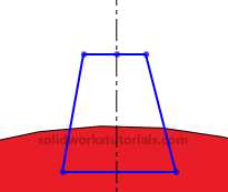
8. Click Line ![]() and sketch gear teeth profile.
and sketch gear teeth profile.
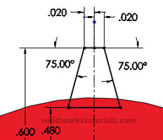
9. Click Smart Dimension,  dimension sketch as sketched below.
10. Click Exit Sketch,  change view to Isometric.

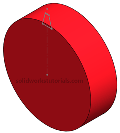
11. Click scroll mouse button and rotate the part to back side.
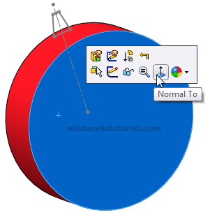
Click the back face and select Normal To. Click on this face again and click Sketch.
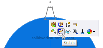
12. We will trace last sketch to this face, while holding CTRL click all sketched line
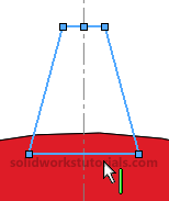 and click Convert Entities
  . Now we need removed all relation between this sketch and the other sketch, click Display/Delete Relations
  click Delete All
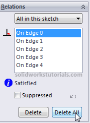
and ![]() .
.
13. Click and drag select all the sketch line.
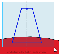
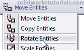
Click on Rotate Entities,
Click Center of Rotation box
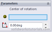
and click origin (center part).
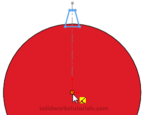
On Parameter option enter 10 deg rotation.
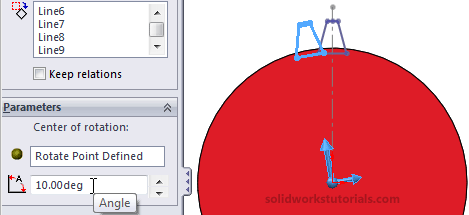
and ![]() .
.
14. Click Exit Sketch,  change view to Isometric.

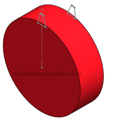
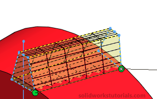
15. Click Features>Lofted Boos/Base,

open up part tree and double click Sketch2 and Sketch3 to add for lofted features.
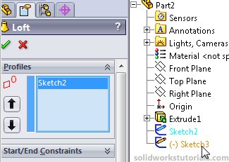
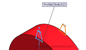
Make sure two green point is at the same edge as other sketch, if not drag and relocate it.

and ![]() .
.
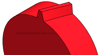
12. Click on Loft1 (gear teeth)  and click Circular Pattern.
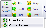
Click on the cylinder face as axis of rotation (or click on View>Temporary Axes select the temporary axis as axis of rotation).
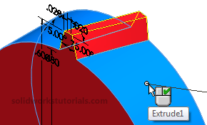
Set Instances to 22 and ![]() .
.
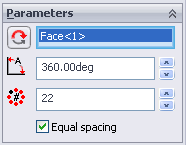
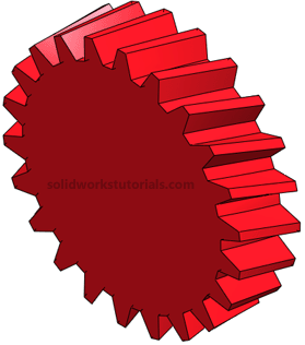
13. Click on Front face and select Normal To.
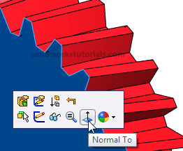
14. Click on front face and select Sketch.
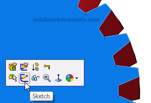
15. Sketch a Circle ![]() and sketch a circle center at origin. Click Smart Dimension,
and sketch a circle center at origin. Click Smart Dimension,  dimension sketch as 0.40in circle.
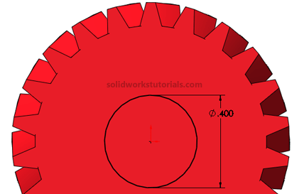
16. Click Features>Extruded Cut ![]() and set Direction to Through All and
and set Direction to Through All and ![]() .
.
17. Click on front face and select Sketch.
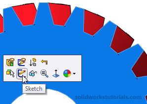
18. Click Rectangle and sketch a rectangle as sketched. Click Smart Dimension,  dimension rectangle as skecthed below.
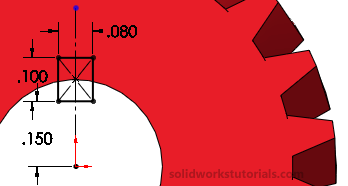
16. Click Features>Extruded Cut ![]() and set Direction to Through All and
and set Direction to Through All and ![]() . You’re done!
. You’re done!

