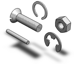
If your SolidWorks package have included Toolbox, if doesn’t have to create any standard part such as screws, pins, gears, clips, nuts, bearing, jig bushings, o-rings and many more! SolidWorks Toolbox have it all. You just drag and drop to your assemblies and set the type and size and you’re done.
Your SolidWorks Toolbox maybe didn’t preloaded when SolidWorks start up, but here the steps how you can load SolidWorks Toolbox;
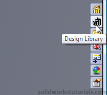
1. Click Design Library tab on you right tab.
[continue reading…]
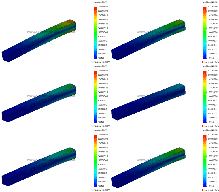
In this tutorial, you will analyze this part using SimulationXpress in solidworks
1. Click New.  Click Part,
  OK.
OK.
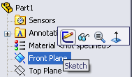
2. Click Front Plane and click on Sketch.
[continue reading…]
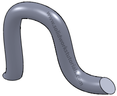
In this tutorials you will create swept part using Swept Boss/Base tool. 
1.Click New.  Click Part,
 OK.
OK.
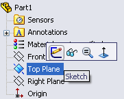
2.Click Top Plane and click on Sketch.
[continue reading…]
Cool transparent part.. Is great for viewing in assembly, have you try it?
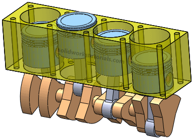
You start with something like this…
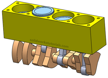
Click on part body and select Appearances
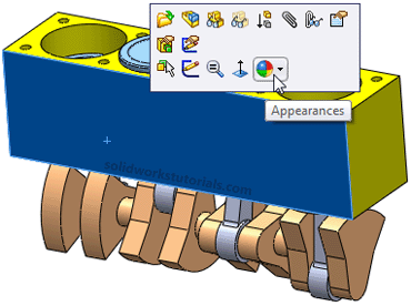
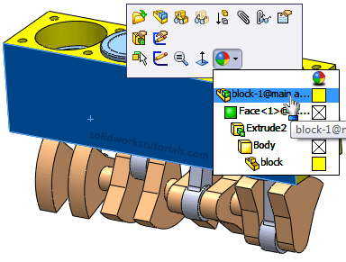
Select the top in the list…
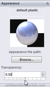
On left side, Appearance, set Transparency to 0.50 and OK.
And you got this.. Give it a try…

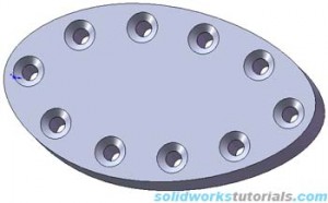
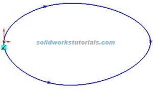
1. Create new part, sketch egg shape on top plane using spline  .
. 
2. Extrude  shape to 0.3in
 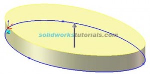 , click top face and right click Insert Sketch.
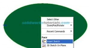
3. Select part edge 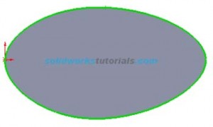 and click offset
  to 0.3in
 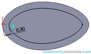 . Exit Sketch
  .
.
4. Click hole wizard  , select Countersink, Ansi Inch, Flat Head Screw, #10, Normal, Through All
 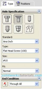 . Click Positions , click screw point at curve edge. OK.
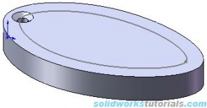
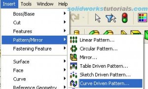
5. Select CSK for #10 Flat Head Machine Screw  , Click Insert>Pattern/Mirror>Curve Driven Pattern…
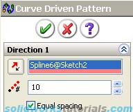
  Define Pattern, select spline sketch and set # to 10, Equal spacing
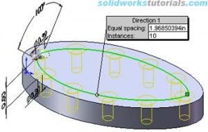 . OK, done.




 , click top face and right click Insert Sketch.
 and click offset
  . Exit Sketch
  .
. . Click Positions , click screw point at curve edge. OK.
 , Click Insert>Pattern/Mirror>Curve Driven Pattern…
  Define Pattern, select spline sketch and set # to 10, Equal spacing
 . OK, done.