For enquiry and help, please contact
support@solidworkstutorials.com
Support Us Donate by PayPal
 in Command Manager, click Rectangle
  . As you can see on upper right corner sketch icon appear indicate that you're on sketch mode.
5. Pick Origin ![]() point as starting point, drag to right hand side
point as starting point, drag to right hand side  no need to be exact the size will define in later step. Press keyboard ESC to end rectangle sketch.
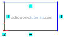
Note: There is two type line generated by your sketching, the one with black line and blue line. Black line is line that fully defined and blue line is under defined.
 , and start dimensioning pick vertical line and set to 2.00in , pick horizontal line and set to 2.00in
  . Press keyboard ESC to end smart dimension.
  and activate features menu. Click Extruded Boss/Base
  and set D1 to 0.5in
  and
and 
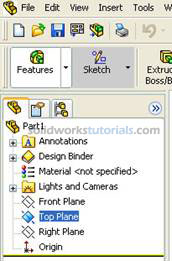
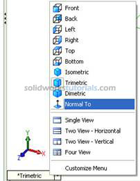
 , click Normal To
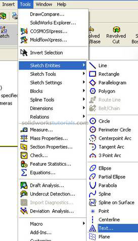
  . Click Tools>Sketch Entities>Text
 to change font type and size uncheck use document font.
  Click Font
 set height to Points 10 OK.
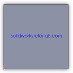
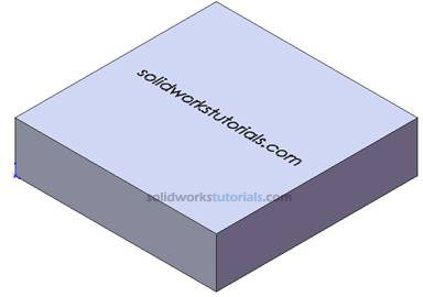
11. To engrave the text, click Features  , click Extruded Cut
  , under Direction 1 Blind, set D1 to 0.01in
  and
and ![]() . Click Isometric
. Click Isometric  from lower left view menu.
Done. Pat yourself on back.
© 2008 solidworkstutorials.com. All rights reserved.